A bearing feeder must deliver the correct bearing without damaging the surfaces needed for assembly. Start with the bearing family, the permitted contact areas and the exact position required at the press or robot pick point.
Speak directly with Sorting Solutions about bearing presentation for automated assembly.
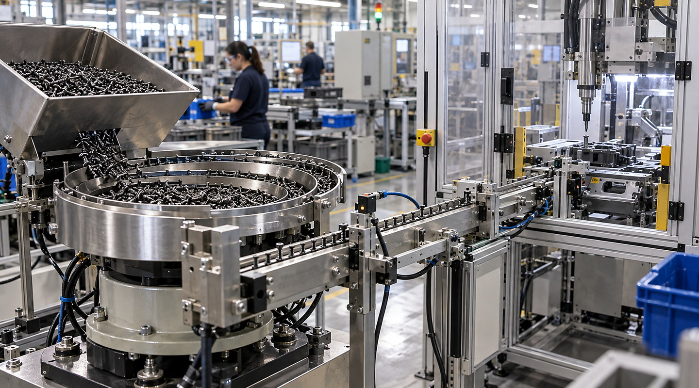
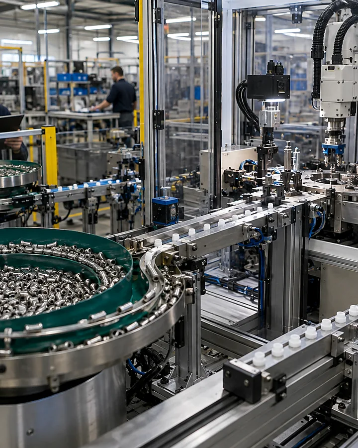
Illustrative component-feeding scene.
Quick answer
Which feeding method suits our bearings and required assembly orientation?
Provide the bearing size range, mass and details of seals or surfaces that must not be damaged. Define whether either face may lead and how the assembly station locates the bearing. Assess singulation and transfer using representative lubricated or packaged parts, including mixed orientation and replenishment conditions.
Record bore, outside diameter, width and mass for each variant. Show seals, shields, flanges or other features that distinguish one face from another. Where bearings look alike, define how the system will prevent a wrong variant reaching the assembly station.
Decision 2
Can the bearing arrive in bulk?
Describe the supplied condition: loose in a tote, stacked, separated in trays or protected in individual packaging. Compare keeping an existing tray presentation with adding bulk handling. Include lubricant, residues and packaging debris in trials rather than using only cleaned demonstration parts.
Decision 3
Where may tooling contact the part?
Identify surfaces that must remain unmarked and any seal or shield that must not carry handling loads. Agree acceptable appearance after repeated circulation and transfer. The feeding trial should examine part condition as well as the number of bearings delivered.
Decision 4
What orientation does the assembly need?
State whether either face may lead, whether a flange must face up and where the receiving tool locates the bearing. A dimensioned hand-off sketch is more useful than “correct orientation”. Include support during transfer so the part does not change pose before insertion.
Decision 5
How will one bearing be released?
Define the receiving machine’s call, ready and occupied states. Check that a queued bearing cannot follow the released part into the assembly position. Agree how an empty track, interrupted cycle or occupied nest is detected and cleared.
Decision 6
What proves the complete route works?
Run the intended variant mix with normal replenishment and downstream stops. Record accepted delivery, incorrect orientation, visible damage and recovery actions separately. Use the existing bearing feeder specification checklist to keep trial conditions attached to the quotation.
Applications
Match presentation to the assembly station
Compare how loose bearings are separated with how the accepted part is released to the assembly tool. The right route depends on the supplied condition, contact limits and receiving-machine demand.
Send drawings, photographs, supplied packaging and representative samples across the size and surface-condition range.
02
Compare presentation routes
Evaluate bulk feeding, metered release or retained tray presentation against the receiving machine and the permitted contact areas.
03
Define the hand-off
Agree the datum, support, single-part release, sensor states and access needed to recover a stopped cycle.
04
Record accepted delivery
Challenge replenishment, variant changes and occupied nests, then compare output and part condition against the agreed limits.
Important limits
Know what needs a separate check
Sample trials must include normal, marginal and supplier-variant components.
Quoted feeder output is not the same as usable delivery at the downstream process.
Fragile, flexible, magnetic or entangling parts may need a different presentation method.
Your final solution for bearing presentation for automated assembly must reflect the law, current standards and site-specific risks that apply to your installation.